
Quick answer: Plan PDR rod access before inserting a tool: confirm current vehicle-specific OEM instructions, identify an existing opening, trace every brace, harness, module, drain, adhesive, foam, and coating along the route, then choose a rod whose length, bend, tip, and handle let the tip contact the low while the shaft clears hidden parts. Protect the leverage point, use controlled movement, inspect repeatedly, and restore any disturbed corrosion protection. Never drill, cut, remove foam, or force a route simply to reach the dent.
Scope: access is part of the repair
This guide covers planning a rear-access push route for paintless dent repair (PDR). It explains how to evaluate existing access, select working geometry, protect the vehicle, and decide when to change method or stop. It does not authorize PDR on a particular vehicle, replace removal-and-installation instructions, define a universal tool angle, or certify that a dent is repairable.
The access route runs from the handle and shaft, past hidden components, across a protected leverage point, and to the tool tip. That complete chain must be verified, controllable, and allowed by current OEM information.
I-CAR says access holes should not be drilled for PDR; if the panel backside requires cutting a hole, PDR is not an acceptable option. It also says foam should not be removed and that an existing opening must not be elongated by tool pressure. Rivian's published repair guideline likewise says not to drill, cut, or modify panels to gain access. These are firm planning boundaries, not inconveniences to work around.
Rod access is only one repair-method option. First determine whether rear access, glue pulling, or a combined route fits the paint, panel, substrate, damage, and OEM restrictions using Push, Pull, or Combine? A PDR Repair-Method Decision Framework.
Start with current OEM repair information
Research the exact year, model, body configuration, panel, and installed equipment before removing trim or feeding a tool into a cavity. Look for vehicle-maker PDR position statements, body repair manuals, material maps, removal-and-installation procedures, corrosion-protection instructions, electrical or high-voltage precautions, one-time-use fastener rules, water-leak checks, and required diagnostics or calibrations.
An OEM statement may permit PDR generally while a vehicle-specific procedure narrows that permission. Rivian says PDR may be used on steel and aluminum, subject to each substrate's limitations and the vehicle Material Matrix. It also requires pre/post paint inspection and corrosion restoration with approved materials. This does not make every dent repairable.
Build an access worksheet before disassembly:
- vehicle identification and configuration;
- panel name, substrate, and layered construction;
- dent location relative to edges, body lines, braces, adhesives, and reinforcements;
- permitted repair method and stated limitations;
- existing access openings and intended entry route;
- trim, lamp, liner, seal, glass, carrier, or module procedures needed for access;
- electrical, restraint, ADAS, battery, and high-voltage precautions;
- fasteners, clips, seals, tapes, and one-time-use parts required for reassembly;
- corrosion-protection material and application requirement;
- post-repair inspection, water test, scan, calibration, or functional check.
If the information is unavailable or ambiguous, pause. A rod fitting through a visible gap is not evidence that the path is approved.
Remove trim and modules by procedure, not by improvisation
A safer route may become available after documented removal of trim, a carrier, lamp, liner, headliner, seal, or molding. Removal can reveal a factory opening and protect a component from rod contact.
I-CAR says adjacent parts may need removal for complete access or protection and emphasizes following removal, installation, and vehicle-maker procedures. Record clips and fasteners, support glass or trim as directed, and preserve the order for reassembly.
A door, roof, quarter, or liftgate can contain airbag wiring, antennas, cameras, latches, mechanisms, sensors, or high-voltage-related components. Follow applicable OEM power-down, handling, scan, and calibration instructions. If the procedure exceeds the technician's training, equipment, or authorization, stop.
After disassembly, inspect the cavity with suitable lighting and, where appropriate, a mirror or camera. Account for removed items and protect connectors and finishes. Partial visibility is not permission to begin pushing.
Map the hidden route before selecting a rod
Trace the shaft envelope from entry to contact, including space needed to pivot, rotate, advance, and withdraw. Static fit does not prove the handle's working movement is safe.
Identify these hidden features:
- Braces and reinforcements: Determine whether the dent is on open skin, beneath a brace, near a hem, or within a layered zone. Do not pry a brace away from the skin or damage an adhesive bond to create clearance.
- Wiring and connectors: Locate harnesses, clips, grounds, terminals, and slack. A rod must not pinch, chafe, hook, stretch, or use wiring as a guide.
- Modules and mechanisms: Map window regulators, locks, latches, airbags, sensors, speakers, antennas, motors, and moving tracks. Check the complete travel range needed for functional testing after reassembly.
- Drains and water paths: Preserve drain openings, membranes, seals, vapor barriers, and designed water routes. Do not use a drain as a leverage point or leave it blocked by displaced material.
- Foam and sound treatment: Identify structural foam, NVH foam, pads, mastics, and sound deadening. I-CAR specifically says foam should not be removed for PDR. Do not cut, dissolve, compress, or relocate it to make a passage.
- Corrosion protection: Note E-coat, wax-based coating, seam sealer, adhesive, and other backside protection that the tip or shaft could disturb.
- Adjacent panel surfaces: The rod can scratch the far side of a cavity, not just the panel being repaired. Include those surfaces in the route assessment.
If the path cannot be observed sufficiently, use a different existing route or another approved repair plan. Blind force is not access planning.
PDR rod access decision table
| Access condition | Route decision | Rod geometry question | Protection requirement | Stop or change signal |
|---|---|---|---|---|
| Open panel backside through an approved existing opening | Use only after the entire working envelope is mapped | Can the shaft reach the low with handle clearance and controlled tip orientation? | Sleeve or pad any permitted contact point and protect nearby finish | Tip position is uncertain or the shaft contacts hidden components |
| Dent near a brace | Look for an OEM-permitted route beside or through an existing opening | Does a suitable bend clear the brace without prying or loading it? | Protect the brace edge and preserve adhesive, foam, and coatings | Brace must be displaced, adhesive disturbed, or tool is trapped |
| Door cavity with trim removed | Confirm glass, regulator, wiring, latch, and drain locations first | Can the rod move through its full correction arc without entering a mechanism's travel? | Follow glass and electrical procedures; preserve membrane and drains | Rod touches glass, harness, regulator, airbag item, or drain path |
| Roof or upper-body access | Follow headliner, restraint, antenna, roof-system, and electrical procedures | Can the handle be controlled without loading roof structure or interior parts? | Protect interior and identify airbags, bows, wiring, foam, and adhesives | Required removal is unsupported or a safety component remains in the path |
| Wheelhouse or lamp opening | Verify liner/lamp removal, seal, connector, and water-path procedures | Will the shaft clear flanges and adjacent surfaces throughout movement? | Protect openings and plan seal/fastener restoration | Seal, connector, coating, or opening would be damaged or enlarged |
| Narrow existing hole | Treat diameter and surrounding structure as fixed | Is there a documented smaller rod and working arc that fits without edge loading? | Use a non-damaging protector if allowed and keep the edge unloaded | Hole must be drilled, cut, elongated, or used as a hard fulcrum |
| Foam or bonded reinforcement blocks the route | Reject that route | Do not select a rod to pierce or displace the obstruction | Preserve foam, adhesive, and reinforcement | Access requires foam removal or bond disturbance |
| Route remains unseen or unidentified | Do not insert the rod | Tool selection cannot solve missing route evidence | Obtain inspection access or change method | Hidden components cannot be accounted for |
This table supports repair planning; it does not override the OEM procedure or prove that a listed route is acceptable on a specific vehicle.
Choose length, bend, and shaft for the verified route
Select a rod after the route has been mapped, not before. Tool geometry should make the desired tip position possible while leaving the handle in a stable working space.
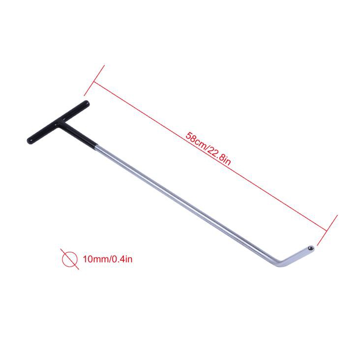
Working length must cover the distance from entry to dent with enough remaining handle clearance for controlled movement. Excess length is not automatically useful. A very long shaft may sweep through a wider hidden envelope, flex more under load, reduce feedback, or make the handle collide with trim, stands, walls, or the technician's body. A short rod may require an unsafe reach, place the handle inside the cavity, or encourage the opening to be used as a hard lever.
Bend geometry establishes how the shaft goes around an obstruction and how the working end approaches the low. Compare the rod's complete shape with the actual cavity; a hook-like end can clear one brace but point the tip away from the target, while a shallow bend can approach the target but leave the shaft against another surface. The correct bend is the one that produces a known contact point and usable handle motion without loading an excluded component.
Shaft diameter and stiffness affect clearance, flex, feedback, and load transfer, but there is no universal best combination. Do not infer capacity from appearance or set weight. A slender rod may reach a restricted route but deflect; a heavier rod may be more direct but need more clearance. Neither should be forced through an opening.
Handle configuration affects orientation and leverage. Fixed, rotating, adjustable, or extendable handles must lock or operate as their manufacturer specifies. Make sure rotation does not bring the shaft into wiring or a brace, and ensure an extension does not create an uncontrolled working radius. Inspect handles, joints, replaceable sections, and locks before use.
Record the manufacturer, model or set, working length, diameter, bend, tip interface, handle, and condition when documented. If geometry is missing, measure the physical tool for planning but do not present that measurement as a manufacturer specification.
Match the tip to contact and repair stage
Tip shape, material, covering, condition, and angle influence how localized the panel input becomes. Broad or padded contact can act differently from a small hard contact, but no tip name guarantees a result.
Choose the tip by answering four questions:
- Can the exact contact point be identified under the reflection?
- Can the tip sit on that point without slipping onto an edge, brace, adhesive, or coating defect?
- Does its documented material and shape suit the intended repair stage and substrate?
- Can the technician limit and observe the movement before making another input?
Inspect removable tips and caps for looseness, cuts, embedded debris, mushrooming, sharp edges, thread damage, or material transfer. A protective cap can reduce direct metal-to-metal contact, but I-CAR notes that repeated tip movement can still remove backside E-coat or wax-based protection even when tips are plastic protected. Treat coating restoration as part of the plan rather than assuming a covered tip leaves no trace.
Do not improvise a tip. An unidentified modification changes contact geometry and may introduce a sharp edge or loose material.
Set the contact angle and verify tip location
The useful working angle is the angle that lets the tip contact the intended low while the shaft and handle remain clear and the input remains controllable. It is not a universal degree value. Panel curvature, dent location, entry point, bend, tip, and available handle travel all change it.
Before meaningful pressure, establish tip location with minimal input under a stable reflection. Confirm from more than one observation position on a complex contour. If the response appears offset, withdraw or reorient the tool; do not search with a loaded tip.
Keep the approach consistent enough that changes in the reflection can be attributed to a specific contact. As the repair progresses, the working low and required contact may change. Re-map the surface, adjust the route or rod, and verify again. How to Read a PDR Line Board explains how a repeatable viewing position helps separate lows, highs, crowns, and unintended movement.
Protect the leverage point
A leverage point is the reaction location that lets handle motion produce controlled tip movement. It may be an approved support tool or a protected existing surface evaluated for the load; apparent rigidity does not prove safety.
Inspect its structural role, coating, flange, seams, glass proximity, wiring, seals, adhesives, and load direction. When procedures allow a protector or leverage accessory, it must remain stable and must not wedge or deform the opening.
Do not lever directly against painted edges, glass, wiring, drains, plastic trim, modules, sharp flanges, unsupported outer skin, foam, adhesive beads, or an unidentified internal surface. Do not let the rod elongate an existing hole. If the reaction point flexes, slips, marks, creaks, changes a gap, or obscures the shaft path, unload immediately.
Leverage does not replace control. More handle travel or a longer lever can multiply input while reducing the technician's margin for detecting a sudden panel response. Use small observable corrections, unload, and inspect.
Nine-step PDR rod access workflow
- Confirm repairability and OEM boundaries. Identify the vehicle, panel, substrate, damage, paint condition, and current vehicle-specific PDR limitations. Reject any plan that requires drilling, cutting, panel modification, or foam removal.
- Research all linked procedures. Collect removal, electrical, restraint, high-voltage, fastener, sealing, corrosion, diagnostic, calibration, and inspection instructions required by the route.
- Map the dent and hidden construction. Locate edges, body lines, braces, reinforcements, adhesive, foam, wiring, drains, mechanisms, modules, glass, and adjacent surfaces.
- Select an existing entry and exit plan. Define how the tool will enter, pivot, work, and withdraw without enlarging the opening or trapping the shaft.
- Remove approved components correctly. Follow the exact procedure, retain fastener identity, protect connectors and finishes, and create sufficient visibility for route inspection.
- Choose rod, tip, angle, and leverage protection. Match the verified cavity to documented tool geometry. Check the complete swept envelope and stabilize the reaction point.
- Verify tip location with minimal input. Observe the panel under a consistent reflection. If the response is not at the intended low, unload and reposition rather than searching under pressure.
- Make one controlled correction, then inspect. Check the front surface, paint, backside, route, leverage point, tool, hidden components, and coatings after each limited movement.
- Restore and verify. Apply required corrosion protection with approved materials, reinstall parts and seals by procedure, complete required scans/calibrations/tests, confirm drains and mechanisms work, and record the repair.
Access examples: reason from the route, not the panel name
Door dent
A door is not automatically accessible through the belt opening. First identify glass position and handling instructions, the regulator and carrier layout, side-impact reinforcement, latch and wiring, moisture barrier, drains, and any side-airbag components. A route through a documented trim-removal opening may offer better visibility than a narrow gap. The rod's bend must clear the reinforcement, while its swept handle motion must not touch glass or the regulator. If the only apparent path requires loading a drain hole, moving a brace, or working blind beside glass, change the plan.
Roof or upper side panel
Roof access can involve headliner procedures, airbags, antennas, lighting, wiring, roof bows, adhesives, foam, and panoramic-roof components. Do not pull down one corner of a headliner and assume the cavity is clear. Follow the full removal or lowering procedure and electrical/restraint precautions. A long rod may reach the dent yet create a wide hidden sweep. If bows, foam, bonded areas, or safety systems block a verified path, use another approved method or stop.
Quarter panel, fender, or lamp opening
An existing lamp, liner, or service opening may provide a route, but seals, harnesses, flanges, and water paths must be restored. Verify reinforcement, foam, and tool withdrawal. Do not turn a drain or body-plug location into a convenient hard fulcrum. Vehicle construction differs by model and configuration.
Corrosion protection is a completion gate
Rod pushing can disturb backside coatings even when the painted front surface remains intact. I-CAR's PDR corrosion guidance says repeated tool-tip contact can remove E-coat or wax-based coating and recommends assuming the finish has been scratched and applying corrosion protection to the panel backside for most PDR repairs. Its broader guidance says OEM procedures control the correct materials and locations.
Plan restoration before the tool is inserted. Confirm which approved material applies, how the area must be prepared, where it must and must not be sprayed, what access equipment is needed, and whether adjacent drains, seams, adhesives, foams, or electrical parts require protection. A generic cavity wax is not automatically a substitute for an OEM-specified product or process.
After application, inspect coverage as permitted, clear drains, reinstall plugs and barriers, and document the material and location. If protection cannot reach the disturbed area, the repair is incomplete.
Stop conditions and common access failures
Stop before or during rod work when:
- current OEM information prohibits the method or cannot be confirmed;
- access requires a new or enlarged hole, cut, panel modification, foam removal, or brace displacement;
- the panel substrate, layered construction, hidden component, or route remains unidentified;
- paint cracks, lifts, changes, or shows another unsafe response;
- the tip location cannot be verified or moves unpredictably;
- the shaft touches glass, wiring, a module, mechanism, seal, drain, foam, adhesive, or excluded surface;
- the leverage point slips, deforms, marks, creaks, or changes an opening or panel gap;
- a tip, cap, handle, joint, extension, or shaft is damaged or loosens;
- more force is being considered only because the route or geometry has not been diagnosed;
- corrosion protection, reassembly, diagnostics, calibration, or functional verification cannot be completed.
Common mistakes include choosing the longest rod first, using a bend by visual similarity, treating an existing hole as a fulcrum, searching for the dent with a loaded tip, removing sound-deadening material, leaving trim partly attached in the working path, and assuming plastic tips eliminate coating damage. Each mistake substitutes tool motion for route evidence.
Verified Super PDR rod-set facts and buyer checklist
Super PDR's verified product inventory provides several documented set examples, but none of those records establishes the exact length, bend, tip, or access coverage needed for a vehicle. The MPT-Q014 page lists a five-piece spring-steel and plastic set with a 2 kg set weight, 360-degree adjustable rotation, an extendable handle, and replaceable lever rods. The MPT-Q013 page lists an eight-piece spring-steel and plastic set with a 2 kg set weight.
The MPT-Q016-B2B page lists a seven-piece spring-steel and plastic set with a 2.5 kg set weight and OEM availability. The MPT-QK0025 page lists a ten-piece set, a 2.5 kg set weight, and a wholesale minimum order quantity of 50 sets. These are scoped packing and commercial facts, not claims that higher piece count, greater weight, or OEM availability produces safer access.
Before selecting or buying a rod set, request:
- a scaled list of each rod's working length, shaft diameter, bend profile, working end, tip interface, and handle type;
- material and finish identification tied to the exact set revision;
- tip, cap, handle, joint, extension, and replacement-part compatibility;
- inspection criteria for straightness, surface defects, damaged ends, locks, threads, and protective parts;
- clear images of the complete rod profile and working tips, not only a grouped set photo;
- packing-list and label revision control for repeat orders;
- instructions for cleaning, storage, corrosion prevention, tip replacement, and retirement;
- a sample check using representative access mockups or the buyer's actual work mix;
- written confirmation of commercial terms for the exact model and order, rather than generalizing one page's MOQ or warranty.
A useful set covers verified route geometries. Piece count alone does not reveal access coverage. For a wider buying framework, see the PDR Tool Selection Guide and Building a PDR Starter Kit.
Frequently asked questions
Can I drill an access hole for a PDR rod?
No. I-CAR says not to drill access holes for PDR and that if a hole must be cut to reach the backside, PDR is not an acceptable option. Rivian also says not to drill, cut, or modify panels for access. Use a verified existing route, another OEM-permitted method, or a different repair plan.
Can an existing drain hole be used as a leverage point?
Do not assume so. The opening and surrounding structure must remain undamaged, and its drainage function must be preserved. I-CAR warns against elongating an existing opening with tool pressure. If a protected, permitted reaction point cannot be established without loading the hole, choose another route or method.
Should I remove foam or sound deadening to reach a dent?
I-CAR specifically says foam should not be removed for PDR because it can be difficult to reinstall correctly. Identify foam, adhesives, and sound-treatment material during route mapping. Do not cut, dissolve, pierce, compress, or relocate them to create access.
How do I choose the correct PDR rod length?
Choose enough working length to reach the mapped low while maintaining handle clearance, tip control, and a safe swept path. Longer is not automatically better; additional length may increase hidden movement, flex, and interference. Verify the full route and the physical tool rather than selecting from panel size alone.
What tip should I use behind the panel?
Match the documented tip shape and material to the current contact objective, substrate, and repair stage. Confirm the tip can be located accurately and inspected between corrections. A protective cap can reduce direct contact but does not guarantee that backside corrosion protection remains intact.
Can I lever a rod against a brace?
Only when the exact point, load direction, protective method, and vehicle/tool procedures make it acceptable. Never pry the brace away from the outer skin, disturb adhesive or foam, damage coatings, or use an unidentified edge. Stop if the support moves, marks, or changes the opening.
What must be checked after reinstalling trim or a module?
Follow the OEM procedure. Typical planning fields include fastener and seal replacement, connector engagement, mechanism travel, water management, required scans or calibrations, and functional checks. Also verify restored corrosion protection, unobstructed drains, clean finishes, and an accounted-for tool and parts inventory.
Ссылки
- I-CAR: What does I-CAR say about drilling holes to perform PDR repairs?
- I-CAR: What does I-CAR say about corrosion protection after PDR?
- I-CAR: Back-To-Basics—Removing Parts for Access
- I-CAR: Corrosion Protection Guidelines
- Rivian Repair Guidelines—Paintless Dent Repair position statement
- Super PDR: MPT-Q014 five-piece rod set
- Super PDR: MPT-Q013 eight-piece rod set
- Super PDR: MPT-Q016-B2B seven-piece rod set
- Super PDR: MPT-QK0025 ten-piece rod set
Technical review note: This article provides general educational guidance. Current vehicle-specific OEM repair information and instructions for the exact vehicle, components, corrosion materials, and PDR tools control the repair.