
Quick answer: Choose a PDR glue tab by matching its contact footprint to the working low, its shape to the dent or body-line direction, its face and stiffness to the planned load, and its connector to the pulling tool. Use broader or more flexible contact for controlled general movement and smaller, more localized contact for refinement, but never treat color, diameter, or physical attachment as proof of performance or compatibility. Inspect paint and OEM limits before bonding, then reassess after every controlled pull.
Scope: tab selection is a force-path decision
This guide begins after the panel has been inspected and glue pulling has been accepted as a possible repair route. It explains how to choose the contact geometry between adhesive and panel. It does not decide whether damaged paint is safe to pull, specify a universal glue or panel temperature, prescribe pull force, or promise that a particular tab size will repair a dent of a stated size. Vehicle-specific OEM procedures and the instructions for the exact adhesive, tab, adapter, and puller control the work.
A glue tab is more than an attachment point. Its face establishes where the adhesive bond contacts the panel; its outline distributes that contact across the low; its stiffness affects how load spreads from the connector toward the edges; and its neck or pulling feature transfers load into the tool. Changing any of those fields changes the force path.
I-CAR says glue pull repair typically requires tabs of different shapes and sizes depending on the dent, and that a repair plan is important regardless of the system used. That is the central selection rule: define the movement first, then choose the tab. See I-CAR's Glue Pull Repair overview.
This narrower task follows the broader route and tool decisions. If glue pulling has not yet been selected, use Push, Pull, or Combine? A PDR Repair-Method Decision Framework. If the pulling mechanism is still undecided, compare it in Slide Hammer vs. Dent Lifter vs. Bridge Puller.
Read the dent footprint before choosing the tab
The visible dent boundary is not automatically the area that should be bonded. First read the panel under a stable reflection and identify the working low: the specific area intended to move during the next correction. Also mark crowns, highs, body lines, edges, paint defects, and areas that move when lightly loaded. A broad dent can contain a much smaller active low; a narrow crease can include a wide tension field outside its visible center.
Describe the footprint in operational terms:
- Round or near-round low: movement radiates around a center, although the panel contour may make the footprint asymmetric.
- Oval low: one axis is longer than the other, so the force path may need directional staging.
- Straight or curved crease: the remaining low follows a line and may change width, depth, or curvature along its length.
- Body-line damage: the target includes a designed contour whose position and surrounding tension must be restored.
- Complex or multi-contour damage: the contact plane changes across the intended bonding area, so a flat rigid face may not make reliable contact.
- Mixed damage: a broad low, sharp center, displaced crown, and previous pull marks may require different tabs at different stages.
Do not select a tab from the overall dent diameter alone. The useful comparison is between the tab face and the low you intend to influence now. A face that extends well beyond the intended working zone can bond to metal that should remain observable or move differently. A face that contacts only a small fraction of a broad low may concentrate load before general shape and surrounding tension have been addressed.
Round tabs versus crease tabs
A round tab is a logical starting shape for a localized round or oval low because it can distribute contact around a central pulling point. It does not guarantee an even result: panel curvature, face design, neck location, stiffness, adhesive coverage, and pull direction still matter. On an oval low, a round tab may be useful for a local stage, while an oval or staged sequence may better follow the longer axis.
A crease tab uses an elongated face to place contact along a line. Its long axis should support the section of crease or body line being corrected, not simply cover the longest possible distance. Straight and curved crease tabs are not interchangeable by name alone. The face must sit against the actual local contour without rocking, bridging a hollow, or forcing one end away from the panel.
For a long crease, divide the repair into observable working zones. A long tab may help move a broader section when its face conforms and the pulling system is designed for that loading. A shorter crease tab may give better control where depth, direction, or curvature changes. Pulling the entire visible crease with one tab can hide which section is moving and which section is locked.
KECO's current 6C process, as manufacturer guidance for its system, says to select a tab shaped to match the dent or body line. Its catalog also separates round, oval, and crease shapes, demonstrating that shape is an engineered field rather than a cosmetic label. Those pages do not establish a universal performance hierarchy for every brand or material.
Size the face to the working low, not the sales label
Tab size should be recorded as actual face dimensions and shape. Labels such as small, medium, large, hail, finishing, or collision are system-specific and cannot be compared reliably across suppliers. A buyer or technician should know the bonded face dimensions, not just the package name.
Use these principles when comparing face size:
- The face should contact the intended working area without covering paint defects, an unsuitable edge, or a zone that must remain free to move.
- The complete face should be able to seat on the local panel contour as its manufacturer intends.
- The selected pulling tool must connect without its feet, bridge, adapter, or body interfering with the tab or adhesive.
- The tab should leave the technician able to observe surrounding movement under the inspection light.
- The face should suit the current repair stage, which may change after each correction.
For steel, KECO's 6C page advises users of its process to keep tabs within the dent edges so secondary damage remains visible. That is useful, attributed process guidance rather than an industry-wide dimensional rule. On any substrate, the safer general principle is to preserve visibility and control: do not let a large bonded footprint obscure the fact that crowns or adjacent metal are reacting incorrectly.
Do not turn tab-to-dent ratios into unsupported formulas. The same apparent dent size can represent different depth, stretch, contour, material, reinforcement, paint history, and crown conditions. A measured dimension can help document a setup, but it cannot replace inspection and OEM information.
Tab face, stiffness, and load distribution
Two tabs with the same outline can load the panel differently. Face texture affects how the adhesive contacts the tab according to that system's design. Face thickness, ribs, edge geometry, neck position, and material stiffness influence how force moves from the connector into the bonded area.
A more rigid tab generally resists conforming to an irregular surface and can transmit load more directly through its designed structure. A more flexible tab can follow curvature or allow the outer face to respond differently, but flexibility is not automatically gentler or weaker. The actual result depends on the tab design, adhesive bond, contour, loading method, and panel response.
KECO distinguishes rigid and flexible materials in its own tab families. Its 6C guidance says flexible tabs often work best on aluminum in its process because they can aid adhesion without locking in crowns. Its Dead Center crease page describes a design with a rigid center and edges intended to flex. These are manufacturer-specific design and technique statements. They must not be converted into claims that a color always identifies stiffness, that all aluminum requires one material, or that one tab prevents overpull.
When product documentation is available, record:
- tab manufacturer and family;
- exact shape and face dimensions;
- straight, curved, hinged, or articulating construction;
- material or stiffness designation defined by that manufacturer;
- face texture and preparation instructions;
- connector or neck type;
- approved adapters and pulling mechanisms;
- intended repair stage or application;
- inspection, cleaning, storage, and retirement criteria.
If those fields are missing, the tab is an unknown component. Do not infer them from plastic color, a similar silhouette, or a shared connector.
Initial pulls versus refinement pulls
Tab selection should evolve as the panel changes. The initial objective may be to recover broad shape, release a locked working area, or establish controlled movement. Later objectives may be to correct a smaller residual low, a short crease segment, or a local transition.
An initial setup often benefits from contact that represents the general movement being attempted. That might be a broader round, oval, crease, flexible, hinged, or multi-point design when the manufacturer supports it and the face conforms completely. The point is not to make the largest possible pull; it is to move enough of the intended area that the next decision becomes clearer.
Refinement usually calls for a smaller decision unit. As the remaining low becomes localized, a smaller or more focused tab can reduce the bonded footprint and make the response easier to attribute. A crease repair may move from a longer tab to shorter sections. A broad low may move from general shape recovery to a round local correction. The puller may also change from impact to progressive or sustained loading.
Do not assume every repair must progress from large to small. A sharp local low may require a controlled local action before a surrounding zone can be addressed; a complex repair may alternate between tabs, crown work, and rear access. The rule is to select for the next observable movement, not to follow a fixed package sequence.
PDR glue-tab decision table
| Current repair condition | Tab direction | Face and stiffness questions | Pulling-system check | Stop or change signal |
|---|---|---|---|---|
| Localized round low | Center a compatible round contact on the intended movement | Does the full face seat on the contour, and is the stiffness documented? | Adapter must engage fully and pull on the planned axis | Edge lifts, tab rocks, or a sharp high forms |
| Oval low | Align the setup with the long and short axes planned for this stage | Would an oval face or staged round contacts preserve better control? | Check articulation and tool clearance from two views | Metal outside the working zone moves first |
| Straight crease segment | Align a crease tab's long axis with the active segment | Does the face fit inside the controllable section without bridging? | Tool and adapter must support the tab's loading method | One end releases, twists, or stops seating |
| Curved body line | Match the local curve, not the whole visible line | Is a curved, hinged, or articulating design documented for the contour? | Verify connector travel as the line changes | Contact is incomplete or the body line moves off path |
| Broad early-stage low | Use a face that represents planned general movement while leaving reactions visible | Is broader or more flexible contact supported by the tab maker? | Confirm the puller can load it evenly without unsafe supports | Crown, edge, or support area moves unpredictably |
| Small residual low | Reduce contact to the remaining decision area | Is a smaller finishing face compatible with the required load? | Use a mechanism capable of restrained, observable input | The correction overshoots or becomes less localized |
| Irregular multi-contour area | Treat each contour or use a documented conforming system | Can the face make complete contact without forced flattening? | Confirm the adapter does not pry the tab sideways | Gaps, rocking, peel, or uneven adhesive witness marks |
| Unknown tab or mixed components | Do not select by appearance | Can manufacturer, dimensions, material, and instructions be verified? | Physical connection alone is insufficient | Compatibility cannot be documented |
This table identifies questions, not guaranteed prescriptions. Paint condition, prior repair, coating, substrate, dent severity, technician competence, and current OEM procedures can remove any option.
Pull direction begins at tab placement
The pull axis runs through the bonded face, connector, adapter, and pulling mechanism. Centering a connector visually does not prove the load will enter the panel in the intended direction. An asymmetric tab, curved face, articulated section, off-center neck, uneven adhesive layer, tilted adapter, or unstable puller can redirect force.
Check the axis from at least two viewing angles. On a simple local low, the first planned movement may be close to normal to the local surface. A crease, edge, crown, or body line can require staged positions and intentional directional control. The exact technique must follow the system and vehicle information; do not twist an attached tool until the connection appears aligned.
Avoid using a tab as a lever unless the manufacturer explicitly designs the system for that load. Side loading can peel the adhesive progressively from one edge, distort the neck, break the face, unload an articulated joint, or move metal beyond the intended zone. If the adapter must be forced, the connector is partly engaged, or the tab visibly bends in an undocumented way before the panel responds, unload and reconfigure.
The pulling mechanism also changes the load. A slide hammer supplies a short dynamic input; a dent lifter uses local reaction feet and progressive lever action; a bridge applies sustained load across a span. Confirm that the exact tab and adapter are intended for the selected mechanism. A hole, thread, slot, or pass-through feature that happens to connect does not prove suitability for impact, sustained tension, or lateral load.
Nine-step glue-tab selection workflow
- Confirm the repair boundary. Check current OEM procedures, panel substrate, paint and coating condition, previous repair evidence, edges, body lines, and corrosion implications before bonding anything.
- Map the complete damage. Under a stable reflection, identify the working low, crowns, highs, contour changes, visible paint defects, and surrounding areas that must remain observable.
- Define one movement objective. State what the next pull is meant to change: broad shape, one crease segment, a body-line section, a localized residual low, or another specific target.
- Choose the contact outline. Match round, oval, straight crease, curved crease, hinged, articulating, or multi-point geometry to that target using the tab manufacturer's instructions.
- Choose face size and stiffness. Confirm actual dimensions, complete contour contact, documented material behavior, face design, and whether the working zone will remain visible.
- Verify the connection chain. Identify the tab, connector, adapter, and puller; confirm intended compatibility, adequate engagement, articulation, clearance, support placement, and travel.
- Align and inspect before loading. View the pull axis from two directions, check that the face is seated as intended, and ensure the tool does not introduce twist or unsafe panel support.
- Make one restrained correction and unload. Follow the exact adhesive and equipment instructions, limit the input, then remove load so the panel, bond, paint, tab, and supports can be inspected.
- Record and revise. Note the tab identity, dimensions, position, tool, direction, response, and stop condition. Keep, reduce, reposition, or change the setup according to observed movement rather than habit.
The reflection must remain consistent across the workflow. How to Read a PDR Line Board explains how a repeatable viewing position helps distinguish the remaining low, nearby highs, and unintended movement.
Paint-risk checks and stop conditions
Glue pulling preserves access to the outside surface, but it still loads the coating through an adhesive connection. Paint history, repair materials, contamination, coatings, chips, cracks, edges, environmental conditions, adhesive setup, and release method can change risk. A tab-selection guide cannot certify the surface.
Stop before bonding if current vehicle guidance prohibits or limits the process, the substrate is unknown, paint is already lifting, visible cracks or chips intersect the planned bond, previous repair makes adhesion risk unacceptable, or the exact products lack usable instructions. Change method or obtain qualified evidence instead of performing a stronger trial.
Stop during the work if:
- the paint changes, lifts, wrinkles, cracks, transfers, or separates;
- the tab rocks, twists, cracks, permanently distorts, or repeatedly releases from one edge;
- the connector or adapter is not fully engaged or begins to damage the tab;
- the puller feet move, mark the finish, or change the panel outside the plan;
- a sharp high, new low, displaced crown, or spreading distortion appears;
- the panel does not respond predictably to limited inputs;
- adhesive witness marks show incomplete or inconsistent face contact;
- more force is being considered only because the setup has not been diagnosed.
Repeated releases are a diagnostic event, not a request for a larger tab or more aggressive puller. Review the entire bond and load chain using product instructions. The PDR Glue Pulling Troubleshooting guide covers cleaning, environmental setup, adhesive behavior, release, and common connection failures in more depth.
Common glue-tab selection mistakes
Choosing by color
Color can identify a material within one manufacturer's documented family, but it is not a cross-brand stiffness or temperature standard. Record the actual manufacturer, family, and material designation.
Matching the tab to the whole visible dent
The next correction may target only one working low. Covering the full visible area can hide secondary movement or bond beyond the controllable zone.
Using the largest face that will fit
Fit is not the same as useful contact. A large face may bridge curvature, cover a crown, interfere with supports, or distribute load outside the next movement objective.
Using a tiny tab to make a hard pull
Concentrating the connection does not automatically create precision. It can localize load before the surrounding shape is ready and can reduce the margin for observing an abrupt response.
Treating physical attachment as compatibility
A tab and puller may connect while the neck, adapter, thread, slot, or face is unsuitable for the loading method. Verify the complete system.
Repeating one tab throughout the repair
The active low and required control change. Re-map the surface and change contact geometry when the decision area changes.
Ignoring incomplete face contact
Forcing a flat tab onto a curved or irregular area does not create a reliable geometry. Use a documented contour-matching solution, divide the repair, or change the method.
Compensating for bond failure with force
A larger hammer, harder impact, or tighter bridge does not solve contamination, coating risk, incorrect face preparation, incomplete contact, bad alignment, or incompatible components.
Kit and buyer compatibility checklist
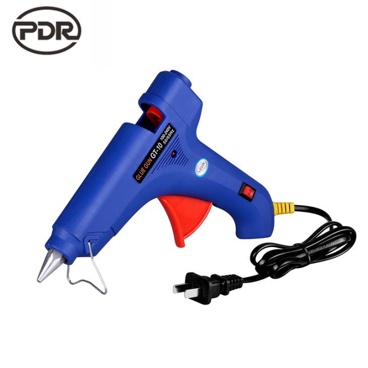
Super PDR's verified product evidence shows that kit contents vary. The MPT-YK0518US wholesale kit lists 20 plastic tabs along with a T-puller, six-piece metal pull set, glue gun, glue sticks, and finishing tools. The verified Super PDR hail-damage set lists 15 glue tabs, a dent puller, dent lifter, glue gun, glue sticks, rubber hammer, and tap-down set. These are packing-list facts, not proof that every tab is interchangeable or suited to every dent.
Before buying or approving a kit, request:
- an itemized tab list with shape, face dimensions, quantity, family, and material designation;
- clear images of tab faces, connectors, necks, and size markings;
- a compatibility matrix for tabs, adapters, lifters, bridges, and slide hammers;
- intended loading methods and repair stages for each family;
- preparation, use, release, cleaning, storage, and inspection instructions;
- replacement SKUs for consumable, lost, worn, or broken tabs;
- clarification of whether tab colors or assortments can change between production runs;
- sample inspection criteria that compare delivered parts with the approved list;
- revision control for substitutions in the tab, adapter, or puller system.
A useful assortment covers distinct contact jobs rather than maximizing piece count. The PDR Tool Selection Guide can help buyers place tabs within the larger inspection, movement, access, and finishing workflow.
Frequently asked questions
Should the glue tab be smaller than the dent?
There is no universal ratio. Compare the face with the current working low, not only the overall visible dent. The face should support the intended movement, seat on the contour, preserve visibility of secondary movement, and follow the exact tab-system guidance. Dent geometry, substrate, crowns, paint condition, and repair stage can all change the selection.
Are round tabs only for round dents?
No. A round tab can be used for a localized stage within more complex damage when its contact geometry supports the planned movement. Oval, crease, curved, hinged, or articulating shapes may represent other footprints better. Select the next force path rather than assigning one tab shape permanently to an entire repair.
When should I use a crease tab?
Consider a crease tab when the active low follows a line and the tab face can align with that segment without bridging or rocking. Match straight or curved geometry to the local contour, confirm the puller and adapter are intended for it, and divide a changing crease into stages rather than assuming one long contact controls everything.
Does a rigid tab pull harder than a flexible tab?
Not as a universal rule. Stiffness changes how a particular design conforms and distributes load, but pull response also depends on face and neck geometry, adhesive, panel contour, material, tool, and direction. Use the manufacturer's definitions and instructions; do not infer performance from color or hand feel alone.
Can one glue tab work with a slide hammer, dent lifter, and bridge puller?
Only if the tab and adapter documentation supports those mechanisms and loading methods. A shared connector does not prove compatibility with dynamic impact, progressive lever action, or sustained tension. Confirm full engagement, articulation, travel, support clearance, and the permitted pull direction before loading.
Why does a tab release from one edge first?
Possible causes include incomplete contour contact, uneven preparation or adhesive coverage, off-axis loading, tab deformation, panel curvature, environmental setup, or a component mismatch. Stop and inspect the face, adhesive witness pattern, axis, and instructions. Do not respond by escalating force before the cause is understood.
When should I change to a smaller tab?
Change when the remaining low becomes more localized and a smaller documented face provides a clearer, controllable decision area. Re-read the panel first. A smaller tab is not automatically safer; it must still seat correctly, match the load, and avoid concentrating force into an unprepared area.
Referanslar
- I-CAR: Glue Pull Repair
- KECO: 6C Glue Pull Repair Process
- KECO: PDR and Collision Glue Tabs
- KECO: Intermediate Glue Tabs
- KECO: Dead Center Crease Glue Tabs
- Super PDR: MPT-YK0518US Wholesale Kit
- Super PDR: Hail Damage Dent Repair Set
Technical review note: This article provides general educational guidance. Current vehicle-specific OEM repair information and the instructions for the exact paint, adhesive, tab, adapter, and pulling tool control the repair.