

Quick answer
Specify a PDR lighting setup by the reflection it produces on the panel, its usable adjustment range, its stability, and its power arrangement. Brightness alone does not establish suitability. A shop should test the complete light, mount, power supply, and working position on representative practice panels before equipping multiple bays.
This guide concerns workstation selection and acceptance. For interpreting the reflection itself, start with how to read a PDR line board.
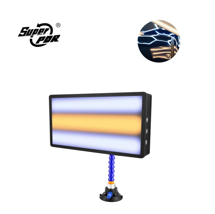
Begin with the jobs the bay must support
A light that works well beside a door may be awkward above a roof or below a curved lower panel. Before comparing products, list the panel positions, technician postures, access routes, and movement space the workstation must accommodate. Include the inspection position as well as the repair position. A technician must be able to move the observation point without repeatedly rebuilding the entire setup.
Separate general workshop illumination from the controlled reflection used to examine surface shape. Both matter, but they serve different purposes. Additional ceiling light does not necessarily improve the contrast of a chosen reflection pattern. Conversely, a readable repair reflection does not mean the rest of the working area is adequately illuminated for safe movement.
Record whether the bay is permanent, shared, or mobile. This determines how much weight to give to stand footprint, setup time, storage, battery changes, and resistance to accidental disturbance.
Write a functional lighting specification
| Requirement | What to record | How to evaluate it |
|---|---|---|
| Reflection control | Available pattern, brightness settings, and supported color settings | Check whether subtle surface changes remain distinguishable without excessive glare |
| Reach and articulation | Positions the complete mount can actually hold | Test the roof, door, and lower-panel positions used in your work |
| Stability | Stand, joints, mounting surface, and cable routing | Observe drift during an ordinary inspection interval |
| Clearance | Stand footprint and technician movement envelope | Confirm that the operator can reposition without contacting the vehicle |
| Power | Exact input, connector, approved supply, and battery configuration | Match labels and instructions; test the intended operating arrangement |
| Serviceability | Replaceable leads, mount parts, diffuser, and power components | Obtain part identities rather than assuming accessories are interchangeable |
These are buyer acceptance fields, not a universal PDR lighting standard. A shop should assign its own thresholds according to the work it performs.
Product listings show why configuration matters. For example, Dentcraft's DNE light listing describes controllable light strips, a dimmer, and a supplied stand. Those are configuration details for that listed product, not minimum requirements or specifications for a SuperPDR light.
Evaluate the complete workstation, not an isolated light head
Use a representative practice panel whose visible features the evaluators already understand. Keep the panel, viewing sequence, and surrounding lighting consistent when comparing candidates. Do not rank lights by photographing each one under a different exposure or in a different room.
Start at a comfortable working position and establish a usable reflection. Then check a second viewing direction, a higher or lower section, and a location near the edge of the available reach. Note whether the mounting mechanism allows precise adjustment or forces the technician into an awkward position.
Assess the setup with the tools and protective equipment normally used in the bay. Cable snags and stand collisions often become apparent only when the operator moves between inspection and repair positions. Record these observations separately from reflection quality. A very clear reflection does not compensate for an unstable mount.
Use a simple comparison record: task, panel location, light settings, mounting position, evaluator, observed limitation, and corrective action. Repeat important observations with a second technician rather than treating one person's preference as a universal finding.
Check power and endurance under a stated condition
For battery operation, define the test before timing it. Record the battery identity, charge state, selected lighting mode, ambient conditions, and any charging or power-bank arrangement. Decide what ends the test: shutdown, a low-battery warning, or illumination that is no longer usable for the agreed task.
Report the result as measured usable time under those conditions. Do not turn one low-brightness test into an all-day runtime claim. An external power source introduces additional dependencies, including its output mode, connector, lead, and the lamp manufacturer's compatibility requirements.
If a lamp performs inconsistently, first distinguish a setting or supply problem from a light-head problem. Replace only with approved, known-compatible components during evaluation. Do not modify plugs, bypass protection, or open powered equipment as part of a buyer acceptance test.
Illustrative two-bay evaluation
Suppose a shop needs one roof-repair bay and one door-repair bay. Candidate A provides a readable reflection in both positions but cannot hold the required roof angle without drifting. Candidate B holds both positions but needs a different approved lead arrangement to keep the walking route clear.
The defensible conclusion is not that B is universally better. It is that A fails the shop's roof-position stability requirement, while B remains conditional until its cable arrangement is validated. A could still be suitable for the door bay if it passes that bay's actual requirements.
This example contains no measured product result. It illustrates why one overall star rating can hide a configuration-specific failure.
Set acceptance rules before ordering multiple units
Define a pass as repeatable readability, stable positioning, suitable clearance, and correct power compatibility for the agreed tasks. A conditional pass should identify a specific unresolved item, such as a mounting accessory awaiting confirmation. Reject a setup that requires unsupported power adapters, cannot hold its position, or repeatedly obstructs safe movement.
Retain the approved configuration with photographs and a parts list. For repeat purchases, compare the light head, mount, connector, controller, and supply against that record. A product with the same appearance may have a different electrical or mechanical configuration.
Recheck the reference setup after relocation, replacement of a critical component, or a reported change in inspection consistency. This is a repeatability check, not a claim that the lamp has undergone laboratory calibration.
Building a SuperPDR enquiry
The SuperPDR dent inspection lamp page provides a relevant starting point for a lighting enquiry. Send the supplier your panel positions, mounting needs, intended supply, and required operating period. Request confirmation for the exact quoted configuration rather than relying on a generic battery-life description.
Keep the purchase specification separate from the technician's repair judgement. Lighting makes an inspection possible; it does not certify paint integrity, repairability, or the quality of work hidden behind the panel.