
Quick answer
Specify PDR workstation lighting by the reflection it produces at the intended panel, the adjustment and mounting range, and the complete power arrangement. Test the light, mount, cable and supply together in representative working positions before equipping multiple bays. Brightness or an advertised runtime alone does not establish whether the setup is suitable for your technicians.
This is a purchasing and acceptance workflow for repair shops, mobile teams and training schools. For the operator’s interpretation of the reflected pattern, use how to read a PDR line board.
Start with the job and the viewing position
A light that works for a small door repair may not cover the positions needed for roof inspection, a long crease or repeated work around a vehicle. Define the representative jobs before comparing equipment. Include the places where the technician and the tool must fit, not only the places where the light can be attached.
- Fixed-bay work: record panel positions, competing overhead light, available mounting surfaces and cable routes.
- Mobile work: record setup space, transport constraints, power availability and the expected interruption pattern.
- Training: include the instructor and trainee viewing positions and the ability to return to a repeatable setup.
- Multi-bay purchasing: specify a repeatable configuration so that replacement mounts, supplies and accessories can be identified.
Use model-specific catalog inputs
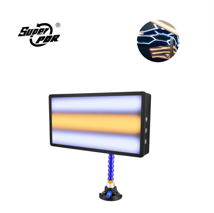
Cái Super PDR MPT-X030-B2B product page provides the following starting inputs, checked on 5 November 2026. These are catalog statements for this model, not measurements from a workshop trial.
| Catalog input | Published information | Buyer check |
|---|---|---|
| Power input | DC 5 V, tolerance plus or minus 0.5 V | Match the actual supplied connector, cable and power source |
| Operating limits listed | Current at or below 2 A; power at or below 10 W | Confirm the requirements on the quoted unit and supplied accessories |
| Light controls | Cool and warm light, with three intensity levels | Try the available settings on representative panel colors and contours |
| Adjustment | A folding, rotating adjustment arrangement | Check usable positions, clearance and stability with the complete mount |
The 5 V input is not a direct 12 V vehicle connection. Confirm a compatible, specified power arrangement rather than adapting a connector by appearance. Treat runtime as a configuration-and-use question: record the actual supply, setting and working pattern for the intended task.
Compare the complete configuration
Separate the light head, mount, base or stand, cable, charger or supply, and battery arrangement in the quotation. A low price for a light head cannot be compared directly with a complete working setup. Record which parts are included and which are optional.
As an example of configuration detail, Dentcraft’s DNE light listing identifies the light head and stand, warm/cool strips and control functions. Those details illustrate useful comparison fields; they are specifications for that listed product, not specifications for a Super PDR lamp.
For a striped reference, compare the Super PDR multi-line reflector board with the lamp on the same panel. The choice should reflect the technician’s ability to read the relevant surface features and keep the work accessible.
A shop acceptance checklist
Agree the tasks and pass criteria before the sample trial. Use representative practice panels and the actual accessories proposed for the order. The following checks define what to observe; the shop should set its required operating duration and working positions for its own workflow.
| Check | Method | Record |
|---|---|---|
| Reflection readability | Observe known surface features and adjacent sound contour under normal bay lighting | Panel, setting, viewing position and whether the required features remain visible |
| Working reach | Set up for representative door, hood and roof tasks | Usable positions and any collision with technician, tool or vehicle |
| Mount stability | Check the intended attachment surface and observe position during normal use | Surface preparation, mount position, drift or slippage |
| Adjustment repeatability | Move away from a recorded setup, then restore it | Whether the operator can recover a useful equivalent view |
| Power arrangement | Use the specified supply and cable; inspect connector fit and cable routing | Supply identity, connector and any interruption in normal operation |
| Runtime suitability | Use the intended setting and duty pattern for the agreed trial period | Start condition, elapsed time, breaks, setting changes and end condition |
| Pack-up and replacement parts | Pack the complete arrangement and identify serviceable accessories | Storage fit, cable protection and replacement identifiers |
If a mount slips, a connector becomes unreliable or an electrical symptom appears, stop the trial and resolve it before use. Do not improvise mounting loads or power connections to force a sample through the checklist.
How to record a useful runtime result
Write down the lamp model, power source, initial charge condition where applicable, cable, intensity and color setting, room conditions and any off periods. Define the endpoint before starting: for example, loss of the usable inspection reflection or the end of the shop’s required operating period.
Distinguish elapsed time from active lighting time. A lamp used intermittently over an afternoon has not demonstrated the same runtime as one operated continuously at the same setting. If the test ends while the lamp still operates, record that it completed the trial period; do not report the time as its maximum runtime.
Repeat the check under the conditions that matter for the purchasing decision. Do not calculate a promised runtime from an unidentified battery or apply one supplier’s battery result to another configuration.
Plan several bays from the task mix
Group the jobs that require a similar view and mount position. A training station, a door-repair bay and a mobile kit may need different accessories even when they share a lamp model. Record the required setup for each station, then identify which components can be standardized.
Keep the accepted sample or configuration record available for incoming inspection. A replacement cable, suction base or power source should match the approved arrangement. For larger orders, agree the inspection plan and exception handling using the tool quality-control guide.
Request a lighting configuration
Send the panel positions, number of workstations, fixed or mobile use, mounting constraints, intended power source and required operating period through the Super PDR enquiry page or email superpdrb2b05@superpdr.com. Ask for the complete MPT-X030-B2B configuration, included accessories and sample terms. Use the line board FAQ for short equipment questions and the B2B FAQ for purchasing details.