
Quick answer
Read a PDR line board by comparing its reflection across sound and damaged areas while keeping the board, panel and viewing position stable. A change in the reflected lines reveals a change in the surface, but line spacing alone does not identify every low or high. Cross-check from another direction, confirm the intended correction and re-read the reflection after each small adjustment.
This guide is for technicians learning dent inspection and finishing control. It explains how to use a reflection as feedback. Equipment procurement and acceptance are covered separately in the PDR workstation lighting guide.
What the reflection tells you
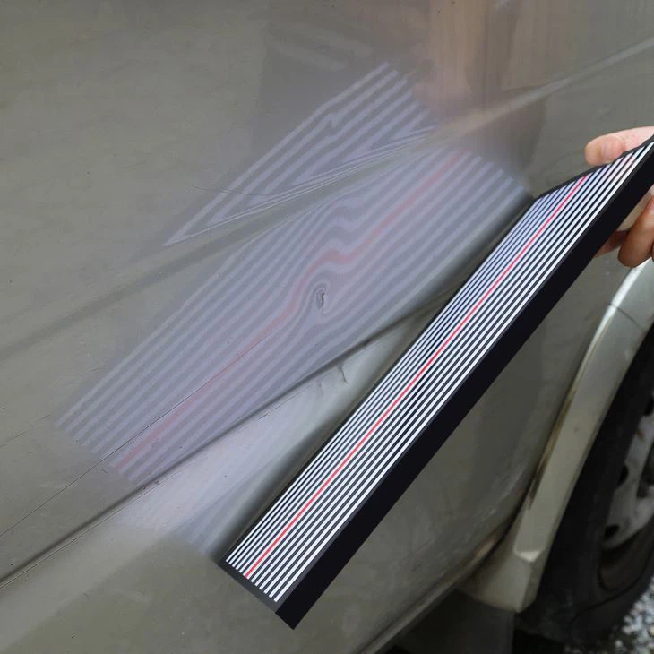
A painted panel reflects the board toward your eyes. Changes in the panel’s local surface angle change where the stripes appear. A dent, a raised area, a factory body line and normal panel curvature can all change the pattern. The useful comparison is with the surrounding intended contour, under a controlled viewing setup.
The board supplies a visible reference, not a ruler for dent depth. Moving your head or the board also changes the reflection. This is why a rule such as “closer lines always mean a low” is incomplete: the appearance depends on the geometry and orientation of the entire setup.
Start by observing a known, undamaged contour and then a known practice defect. Learn how the same feature appears when the board is rotated or viewed from another side. Do not use an unfamiliar reflection pattern as permission to push or pull a customer panel.
Set up the view before moving metal
- Inspect the coating and panel. Identify visible paint damage, previous repairs, body lines and access restrictions before selecting a repair method.
- Position the board securely. Keep its reflection across the repair area and adjacent sound surface. The board should not drift while you operate a tool.
- Choose a useful viewing position. Move until you can follow the reflected lines through and beyond the defect. Keep that position stable for the initial comparison.
- Reduce competing reflections. Adjust the board or work position if windows, overhead lights or bright objects obscure the pattern.
- Map the whole deformation. Observe the center, surrounding transition, any raised perimeter and nearby factory contour. Do not treat the darkest-looking point as the complete repair.
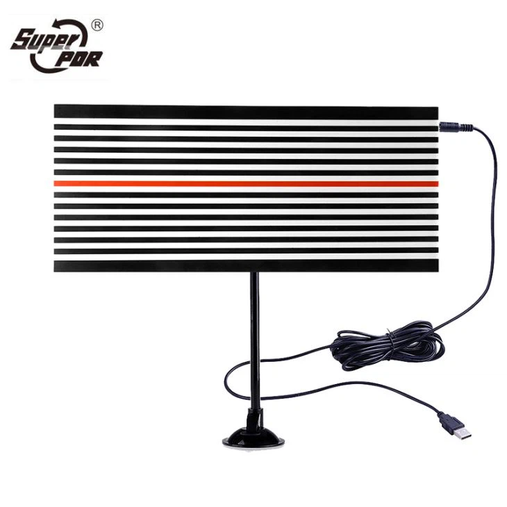
Cái Super PDR multi-line reflector board shown here provides a striped reference. The MPT-X030-B2B inspection lamp offers another lighting configuration. Select the view that lets the technician distinguish the surface features at the intended working position.
Distinguish a low, a high and normal curvature
A low sits below the intended local contour; a high sits above it. A crown describes raised or stressed material surrounding part of a dent. Their appearance must be interpreted in relation to the undamaged shape, especially near a body line or panel edge.
| Observation | What to check next | Mistake to avoid |
|---|---|---|
| A localized kink or compression in the pattern | Compare adjacent contour and inspect from a second direction | Assigning “low” or “high” from spacing alone |
| A broad change around the dent center | Map the surrounding transition and possible crown | Working only at the center |
| A regular bend following a factory body line | Compare the same design feature outside the damaged area | Flattening the intended shape |
| A very small change after a tool adjustment | Confirm the board and eye position stayed stable | Confusing setup movement with metal movement |
| A smooth view from one angle but a disturbance from another | Continue inspection from both directions | Accepting the repair from a single favorable view |
Use a second viewing direction to challenge the first reading
After the initial inspection, change the board orientation or your viewing direction and locate the same feature again. Keep track of the feature on the panel, rather than chasing a reflection that has moved. A second view helps expose a narrow crease or a remaining disturbance that was difficult to see in the first.
Changing board distance also changes the apparent spacing and sensitivity of the pattern. Adjust it deliberately for the task, then establish a new baseline. Do not compare two photographs taken from different setups as though the difference were a direct measurement of repair progress.
For training, use a practice panel with identified defects. Ask the trainee to point out the same defect from two viewing directions and explain the surrounding contour before introducing a tool. That separates recognition of the feature from control of the correction.
Read continuously during pushing, pulling and finishing
Before a push, a trained operator needs to locate the tool’s contact point in relation to the visible feature and understand the available access. Use small, controlled adjustments, then pause to inspect the response. If the contact point cannot be located reliably, stop and reset the view or access.
Before a glue pull, map the affected area and the surrounding surface. After the pull, remove the tab according to the adhesive instructions and inspect again. A tab releasing is an event in the adhesive process, not proof that the panel has reached its intended shape. Use the glue-pulling troubleshooting guide if the bond or movement is unexpected.
During finishing, check the transition into sound metal as well as the original center. A small remaining high can be difficult to see from the position that made the original low most obvious. Only continue a correction when the location and direction of the required change are clear.
Line board or fog-style light?
A striped board provides distinct line boundaries; a fog-style light provides a gradient that technicians can use to read surface transitions. Technician familiarity, panel color, damage location and the available view all matter. KECO’s line-board versus fog-board explanation also treats the choice as task- and technician-dependent rather than a universal ranking.
Evaluate the actual reflection on representative panels. A brighter lamp or a more complicated stripe pattern is useful only if it helps the technician identify and control the relevant features.
Final inspection and a repeatable training record
- Inspect the original damage and its surrounding transition from more than one direction.
- Check that factory body lines and adjacent panel contours remain coherent.
- Review paint condition separately from the metal shape.
- Use both the controlled inspection light and relevant normal viewing conditions.
- For photographs, record the panel, board position and viewing direction; keep these consistent when comparing progress.
A useful practice record identifies the panel, defect, board or lamp, viewing directions, correction attempted and remaining visible feature. Describe observations rather than assigning a numerical depth from an uncalibrated reflection. For more on repair scope, see which dents can be repaired with PDR.
Choose a board for the work position
Send the intended panel positions, mobile or fixed-bay use, mounting needs and power arrangement through the Super PDR enquiry page or email superpdrb2b05@superpdr.com. Compare the multi-line board and MPT-X030-B2B lamp against the reflection and adjustment range your technicians need. Quick equipment questions are covered in the PDR line board FAQ.